Electrical engineers aware that power system was much cleaner and follows the fundamental waveform, thus straightforward. Most of the loads were linear as there was not much automation happened in the industry. Hence switching of such loads was so smooth and there was no pollution like harmonics or any other diseases in power system.
LINEAR LOAD: Load that draws instantaneously proportional current to the applied voltage i.e., constant impedance maintained along the whole alternating period. Examples of linear loads are resistive (electric heaters, incandescent light bulbs)
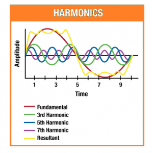
1.HARMONICS AND NONLINEAR LOADS
But nowadays power quality has been changed a lot as harmonic distortion is a regular occurrence in power system. One can get a better understanding in power quality by analysing the real issues, finding the problem occurred and planning the remedial measures for the reduction of power quality distortion
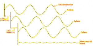
Fig 1 shows balanced single-phase linear loads. Since the loads are linear and balanced there is little or no current flows in the neutral conductor.
But in nonlinear electronic loads, during the conversion of AC to DC there is a need of switching ON of power electronic devices for a fraction of each half cycle. Nonlinear loads draw short bursts of current, which creates a situation where current is not proportional to voltage. This creates harmonic distortion that can have adverse effect on our equipment.
Some examples of nonlinear loads that can generate harmonic currents are UPS, Variable Frequency Drives, Induction furnaces, computers, Hospital Equipment’s, Servo Drives, DC Motors and it controls, PLC’s, and electronic lighting ballasts as they incorporate with switched- mode power supplies. Also, include arcing devices such as arc furnaces, welders.
Finally, we understood that nonlinear loads are the primary cause of harmonics in electrical system and they have extreme harmonic content.
NOTE: The flow of harmonic currents through the system impedance (inductive reactance) causes voltage distortion. Thus, amount of voltage distortion mainly depends on the system impedance and amount of distorted current.
2.CHARACTERISTICS
Harmonics can be classified according to its phase rotation with fundamental as mentioned in the below table,
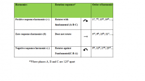
Positive sequence harmonics have the same phase rotation than the fundamental and circulate between the phases.
- Results in substantial increase in losses and temperature rise
- Causes overheating of conductors, power lines and transformers
- Causes skin effect due to the flow of higher frequency currents near the surface of conductor
- Malfunction of communication system
- Occurrence of harmonic resonance
Negative sequence harmonics have the opposite phase rotation than the fundamental and circulate between the phases.
- This opposite phase rotation weakens the required rotating magnetic field of motor and thereby causing them to produce the less mechanical torque. Result in increased heating of motors and reduced torque
- Generates higher temperature and can damage the insulation of the machines, Cable, Transformers, Switch and control gears.
Zero sequence harmonics are on phase with the fundamental and circulate between the phases and neutral. It is also called as triplen harmonics.
- Current in the neutral wire could be 3 times the amplitude of the phase current at the fundamental frequency
- Neutral become less efficient and overheat
- Affects the performance of protective relays
- Nuisance tripping of circuit breaker
3.HARMONIC ISSUES
Harmonic current causes losses in power system which makes overload in distribution system. So, we need to be aware of preventing the system with additional loads in future.
The distribution system harmonics have the following detrimental effects,
- Overheating in stator and rotor circuits of rotating machines such as engine and generator and makes efficiency lower. Hence needs to be the higher size most of the cases
- Increased Iron and copper losses in transformer increased hysteresis and eddy current losses
- Increased skin effect
- Decreased KVA capacity of the transformer
- Overloading of neutral
- Unacceptable neutral to ground voltages
- Distorted voltage and current waveform
- Tripping of breakers and fuses
- Low true power factor by complicating the application of capacitor for power factor correction
- Wherein Kvah Billing applied very high energy bill will occur
- Malfunction of protection system
- Erratic function of automation controls, communication errors
- Unexpected failure/premature ageing of electronic components, Server crash, Data corruption etc.,
Distortion component caused by the harmonics are difficult to detect and required advanced electronic instruments to perform the measurement.
These issues are prevented only by following the given electrical standards. The Information Technology Industry Council (ITIC) recommends the neutrals in the supply to electrical equipment be oversized to at least 173% of the ampacity of the phase conductors to prevent the problems and also recommends derating transformers, loading them to not more than 50% to 70% of the nameplate KVA, based on a rule-of-thumb calculation, to compensate for harmonic heating effects.
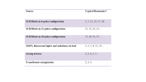
Table 1 shows the typical harmonic orders from a variety of harmonic generating sources.
4.HARMONIC STANDARDS
Standard IEEE 519-2014 indicates the limits of current distortion allowed at the PCC (Point of Common Coupling) point on the system where the current distortion is calculated. This standard is more focused on harmonic limits on the system over time. It now clearly indicates that the PCC is the point of connection to the utility or can be said metering point of utility to the consumer.
Table 2– Utility or Co-generator Supply Voltage Harmonic Limits
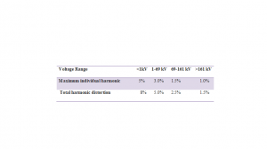
Percentages are (Vh/V1)*100 for each harmonic and:
It is important for the system designer to know the harmonic content of the utility’s supply voltage because it will affect the harmonic distortion of the system.
Table 3 – Current Distortion Limits for General Distribution Systems (120–69,000 V) as per IEEE 519-2014
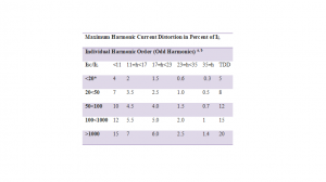
aEven harmonics are limited to 25% of the odd harmonic limits above.
bCurrent distortions that result in a DC offset, e.g., half-wave converters, are not allowed.
*All power generation equipment is limited to these values of current distortion, regardless of actual ISC/IL
where
- ISC= Maximum short-circuit current at PCC.
- IL= Maximum demand load current (fundamental frequency component) at PCC.
- TDD= Total Demand Distortion.
When evaluating current distortion, it is important to understand the difference between THD (Total Harmonic Distortion) and TDD (Total Demand Distortion).
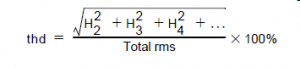
THD is the measured distortion on the actual magnitude of current flowing at a given instant. This could be referred to as a “sine wave quality factor” as it is a measure of the amount of distortion at that given time, for that given magnitude of current. It can be measured with a simple harmonic current metering device.
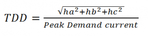
Current THD is not utilized anywhere in the IEEE 519 standard. Instead, the IEEE 519 standard sets limits based on TDD, or Total Demand Distortion. TDD is a calculated value based on the amount of harmonic distortion related to the full load capacity of the electrical system. The formula for calculating TDD is as follows:
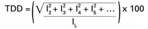
The numerator of the formula is the square root of the sum of the current harmonics squared. This value is divided by IL, which is the full load capacity of the system. From this, you can see that even heavily distorted currents (i.e., high current THD) that are only a small fraction of the capacity of the system will result in a low TDD.
WHY TDD? NOT THD!
Commonly the waveform distortion level is measured by the method of Total harmonic distortion. THD measurements are an effective method of evaluating voltage distortion. However, THD can be misleading when evaluating current distortion.
THD is the summation of harmonics presented as a percentage of the fundamental. For voltage THD this will be the summation of the voltage harmonics compared to the fundamental voltage. In a non-faulted condition voltage will always be present so a proper reference will always exist.
The same is not true for current THD.
Current THD will be the summation of current harmonics compared to the fundamental current. The issue is that fundamental current can change throughout the recording as loads turns on and off. If loads get turned off the fundamental current drops. This is being used as reference even noise on the system will be displayed as high levels of THD when the fundamental reference approaches zero.
This is why TDD is used for measuring current distortions. TDD is the summation of the current harmonics compared to the maximum average current recorded during the test interval. This means that even when the current is low the TDD value will not give misleading results. This methodology is defined in IEEE 519.
If you know the thd and “true” RMS currents, you can derive ha, hb, and hc necessary to calculate TDD.
Thus, for phase A
thdA = sqrt(H2A2 + H2A3 + H2A4 + ….)/I RMS, A1 * 100%
ha = (thdA * I RMS, A1 )/100%
For phase B
thdB = sqrt(H2B2 + H2B3 + H2B4 + ….)/I RMS,B1 * 100%
hb = (thdB * I RMS,B1 )/100%
For phase C
thdC = sqrt(H2C2 + H2C3 + H2C4 + ….)/I RMS,C1 * 100%
hc = (thdC * I RMS,C1 )/100%
Where
- I RMS, A1 is the “true” current for phase A
- I RMS,B1 is the “true” current for phase B
- I RMS,C1 is the “true” current for phase C
From that point,
You can multiply TDD by 100% get obtain a percentage.